
Nowadays multi-processor systems is becoming more and more common especially in high performance computing.
Things become interesting when you think about it from PCI Bus perspective: We use to model it as one PCI host bridge (root complex) yet now we may face the case where there are multiple PCI root bridges.
So yes root bridge is no longer the “root” or at least not the only “root” and we have to move away from the simple logic of assigning Bus 0, Device 0, Function 0 to that device.
What’s more, now they may each can connect to their own pool of memory chipsets how would you decide on what memory/io resource range to give to each of them?
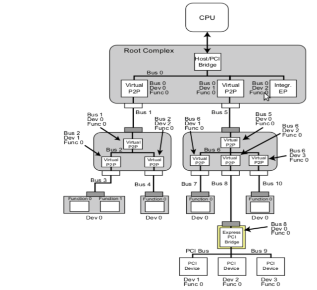
Visually we can see their difference demonstrated as below.
First single root complex:
Then the dual root complex one:
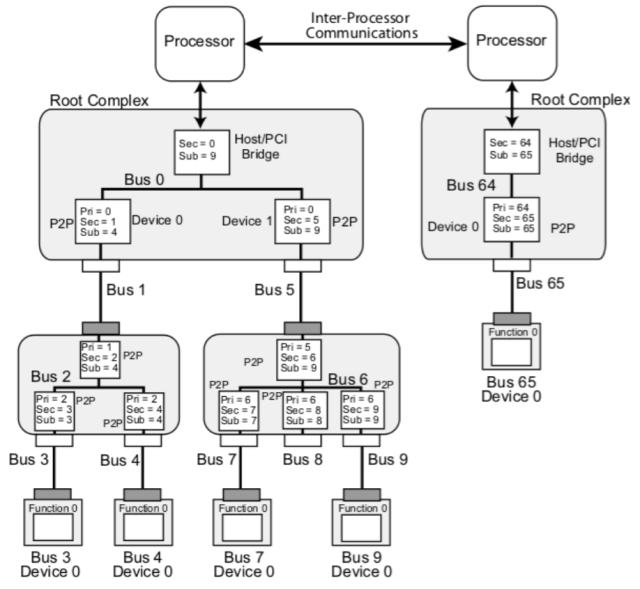
As is shown, for the dual root complex case, the second root complex starts from some non-zero PCI bus number – and in this case Bus 64.
How is this done under the cover? How can standard PCI enumeration process able to see them on the bus number 64?
The ultimate answer goes to the box’s BIOS system which initializes various hardware and assigns the bus number.
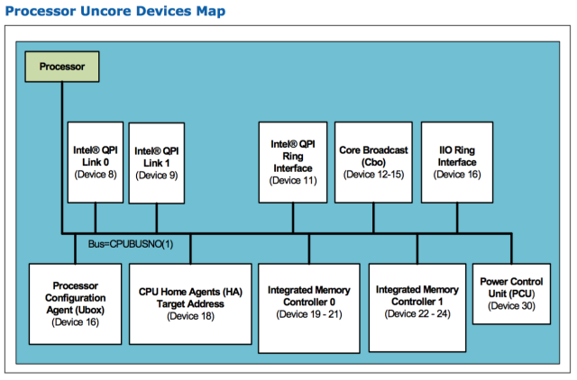
And root-complex nowadays actually becomes part of processor and the process is now divided into core part and “uncore” part, as is shown below:
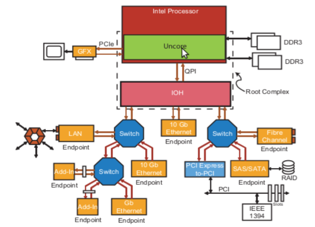
So assigning bus number actually becomes setting some register on the processor.
Below is the PCI device created by the processor for both the core part and uncore part, sitting on CPUBUSNO0 and CPUBUSNO1 separately (taken from Intel Processor datasheet):
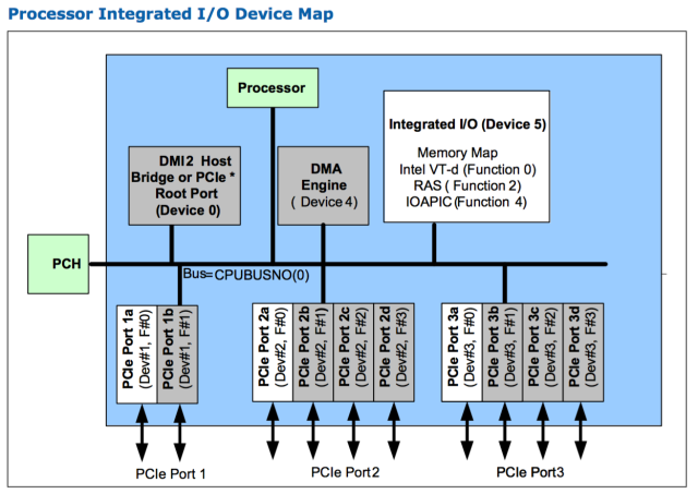
And CPUBUSNO0, CPUBUSNO1 is programmed into the PCI config register of a certain device:
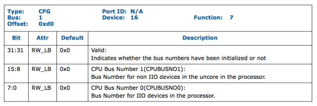
So BIOS has programmed the processor register correctly and if we have multiple processor we can carefully give each of them different bus number and make sure no overlapping.
What happens next?
So there is still one step away from we can take it easy – we have to somehow pass this info to operating system so it knows which devices are the root complex and potentially how much memory chips is installed or neighboring to each host bridge.
There are old hacky ways and standard ways and here we only talk about the standard and recommended way, that is, via Advanced Configuration and Power Management Interface(ACPI).
So in ACPI we can describe all the system devices and its assigned resources.
Devices are normally given some sort of ID such as HID or CID and we can tell whether it is a host bridge by checking specific ID.
For example below is a dump of DSDT tables from my centos system describing the only Host Bridge I have:
Device (PCI0)
{
Name (_HID, EisaId ("PNP0A03") /* PCI Bus */) // _HID: Hardware ID
Method (_ADR, 0, NotSerialized) // _ADR: Address
{
Return (HBCA) /* \HBCA */
}

Name (_BBN, Zero) // _BBN: BIOS Bus Number
Name (_UID, Zero) // _UID: Unique ID
...
Sometimes you may see it differently by highlighting it’s a PCI Express device:
Device (PCI0)
{
Name (_HID, EisaId ("PNP0A08") /* PCI Express Bus */) // _HID: Hardware ID
Name (_HID, EisaId ("PNP0A03") /* PCI Bus */) // _HID: Compatible ID
...
So if your system has multiple root-complex you will see multiple such devices with ID PNP0A03.
What differentiate them from each other would be another important declaration in ACPI method _CSR, i.e. assigned resources.
And for our purpose we are most interested in PCI bus numbers so below is an example in dual root-complex system where for CPU0:
- core devices get CPUBUSNO0=0x0, so a host bridge with bus range 0x0~0x7e
- uncore devices get CPUBUS1=0x7f, so a host bridge with bus range 0x7f-0x7f
And for CPU1:
- core devices get CPUBUSNO0=0x0, so a host bridge with bus range 0x80~0xfe
- uncore devices get CPUBUS1=0x7f, so a host bridge with bus range 0xff-0xff
The ACPI table declaration would be similar to:
Device (PCI0)
{
   Name (_HID, EisaId ("PNP0A08") /* PCI Express Bus */) // _HID:Hardware ID
   Name (_HID, EisaId ("PNP0A03") /* PCI Bus */) // _HID: Compatible ID
   ...

   Name (PCI0Resource, ResourceTemplate ()
   {
      WordBusNumber (ResourceProducer, MinFixed, MaxFixed, PosDecode,
           0x0000,   //Granularity
           0x0000,   // Range Minimum
           0x007E,   // Range Maximum
           0x0000,   // Translation offset
           0x007F,   // Length
           ,, )
       ...
     }
   Method (_CRS, 0, NotSerialized)  // _CRS: Current Resource Settings

   {
      Return (PCI0Resource)
   }
}

Device (PCI0Uncore)
{
   Name (_HID, EisaId ("PNP0A08") /* PCI Express Bus */) // _HID:Hardware ID
   Name (_HID, EisaId ("PNP0A03") /* PCI Bus */) // _HID: Compatible ID
   ...


   Method (_CRS, 0, NotSerialized)  // _CRS: Current Resource Settings

   {
    WordBusNumber (ResourceProducer, MinFixed, MaxFixed, PosDecode,
           0x0000,   //Granularity
           0x007F,   // Range Minimum
           0x007F,   // Range Maximum
           0x0000,   // Translation offset
           0x0001,   // Length
           ,, )
   }
  }

Device (PCI1)
{
   Name (_HID, EisaId ("PNP0A08") /* PCI Express Bus */) // _HID:Hardware ID
   Name (_HID, EisaId ("PNP0A03") /* PCI Bus */) // _HID: Compatible ID
   ...

   Name (PCI1Resource, ResourceTemplate ()
   {
      WordBusNumber (ResourceProducer, MinFixed, MaxFixed, PosDecode,
           0x0000,   //Granularity
           0x0080,   // Range Minimum
           0x00FE,   // Range Maximum
           0x0000,   // Translation offset
           0x007F,   // Length
           ,, )
       ...
     }
   Method (_CRS, 0, NotSerialized)  // _CRS: Current Resource Settings

   {
      Return (PCI1Resource)
   }
}

Device (PCI1Uncore)
{
   Name (_HID, EisaId ("PNP0A08") /* PCI Express Bus */) // _HID:Hardware ID
   Name (_HID, EisaId ("PNP0A03") /* PCI Bus */) // _HID: Compatible ID
   ...


   Method (_CRS, 0, NotSerialized)  // _CRS: Current Resource Settings

   {
    WordBusNumber (ResourceProducer, MinFixed, MaxFixed, PosDecode,
           0x0000,   //Granularity
           0x00FF,   // Range Minimum
           0x00FF,   // Range Maximum
           0x0000,   // Translation offset
           0x0001,   // Length
           ,, )
   }
  }
So in total 4 devices will be described by ACPI.
Here we only show PCI Bus range as a sort of Resource returned by _CRS but there are other resources which are equally critical such as memory/io resources described by ACPI as well.
Now we have the data in ACPI ready for OS to pick up, what’s next?
Let’s look at some linux kernel code that parses those.
First the PCI Host Bridge device is controlled by a special root handler:
static struct acpi_scan_handler pci_root_handler = {
    .ids = root_device_ids,
    .attach = acpi_pci_root_add,
    .detach = acpi_pci_root_remove,
    .hotplug = {
        .enabled = true,
        .scan_dependent = acpi_pci_root_scan_dependent,
    },
};
And there are special IDS that needs to be matched to check if it’s root bridge device.
And not surprisingly it’s familiar “PNP0A03”:
static const struct acpi_device_id root_device_ids[] = {
    {"PNP0A03", 0},
    {"", 0},
};
...
/**
 * acpi_is_root_bridge - determine whether an ACPI CA node is a PCI root bridge
 * @handle - the ACPI CA node in question.
 *
 * Note: we could make this API take a struct acpi_device * instead, but
 * for now, it's more convenient to operate on an acpi_handle.
 */
int acpi_is_root_bridge(acpi_handle handle)
{
    int ret;
    struct acpi_device *device;

    ret = acpi_bus_get_device(handle, &device);
    if (ret)
        return 0;

    ret = acpi_match_device_ids(device, root_device_ids);
    if (ret)
        return 0;
    else
        return 1;
}
Once we match a device we went on to check its resource to find the bus range so as to do proper initializations:
tatic int acpi_pci_root_add(struct acpi_device *device,
                 const struct acpi_device_id *not_used)
{
    unsigned long long segment, bus;
    acpi_status status;
    int result;
    struct acpi_pci_root *root;
    acpi_handle handle = device->handle;
    int no_aspm = 0, clear_aspm = 0;

    root = kzalloc(sizeof(struct acpi_pci_root), GFP_KERNEL);
    if (!root)
        return -ENOMEM;

    ...

    /* Check _CRS first, then _BBN.  If no _BBN, default to zero. */
    root->secondary.flags = IORESOURCE_BUS;
    status = try_get_root_bridge_busnr(handle, &root->secondary);
    if (ACPI_FAILURE(status)) {
        /*
         * We need both the start and end of the downstream bus range
         * to interpret _CBA (MMCONFIG base address), so it really is
         * supposed to be in _CRS.  If we don't find it there, all we         * can do is assume [_BBN-0xFF] or [0-0xFF].
         */
        root->secondary.end = 0xFF;

...
Later in the same function, once we find those root-bridges we are going to head down the bus hierarchy to do the normal PCI bus enumeration:
   /*
     * Scan the Root Bridge
     * --------------------
     * Must do this prior to any attempt to bind the root device, as the
     * PCI namespace does not get created until this call is made (and
     * thus the root bridge's pci_dev does not exist).
     */
    root->bus = pci_acpi_scan_root(root);
    if (!root->bus) {
        dev_err(&device->dev,
            "Bus %04x:%02x not present in PCI namespace\n",
            root->segment, (unsigned int)root->secondary.start);
        device->driver_data = NULL;
        result = -ENODEV;
        goto end;
    }
And as usual you can always spot those devices in sysfs:
$ls -ld /sys/class/pci_bus/*/device/*
drwxr-xr-x. 3 root root    0 Nov 28 23:06 /sys/class/pci_bus/0000:00/device/0000:00:00.0
drwxr-xr-x. 3 root root    0 Nov 28 23:06 /sys/class/pci_bus/0000:00/device/0000:00:01.0
drwxr-xr-x. 5 root root    0 Nov 28 23:06 /sys/class/pci_bus/0000:00/device/0000:00:01.1
drwxr-xr-x. 4 root root    0 Nov 28 23:06 /sys/class/pci_bus/0000:00/device/0000:00:02.0
drwxr-xr-x. 4 root root    0 Nov 28 23:06 /sys/class/pci_bus/0000:00/device/0000:00:03.0
drwxr-xr-x. 4 root root    0 Nov 28 23:06 /sys/class/pci_bus/0000:00/device/0000:00:04.0
drwxr-xr-x. 5 root root    0 Nov 28 23:06 /sys/class/pci_bus/0000:00/device/0000:00:05.0
drwxr-xr-x. 5 root root    0 Nov 28 23:06 /sys/class/pci_bus/0000:00/device/0000:00:06.0
drwxr-xr-x. 3 root root    0 Nov 28 23:06 /sys/class/pci_bus/0000:00/device/0000:00:07.0
drwxr-xr-x. 4 root root    0 Nov 28 23:06 /sys/class/pci_bus/0000:00/device/0000:00:0d.0
lrwxrwxrwx. 1 root root    0 Nov 29 00:09 /sys/class/pci_bus/0000:00/device/firmware_node -> ../LNXSYSTM:00/device:00/PNP0A03:00
drwxr-xr-x. 3 root root    0 Nov 28 23:06 /sys/class/pci_bus/0000:00/device/pci_bus
drwxr-xr-x. 2 root root    0 Nov 29 00:09 /sys/class/pci_bus/0000:00/device/power
-rw-r--r--. 1 root root 4096 Nov 28 23:06 /sys/class/pci_bus/0000:00/device/uevent

In the processor integrated IO devicemap, does root port 1-3 each have their own root complex or is it one root complex for all of them?
In the IO device map, does ports 1-3 share a root complex or have a root complex for each?
This is the very information I was really looking for.
Great organization and nice presentation.
Thanks a lot!
@Jimmy Manley
Each processor has the PCIe lanes directly connected into it. Root complex is eliminated in such system – SoC. Instead, the rest functionalities traditional root complex has is merged into PCH together with southbridge.
And for CPU1:
core devices get CPUBUSNO0=0x0, so a host bridge with bus range 0x80~0xfe
Shouldn’t this text read
………………..get CPUBUSNO0=0x80, ……….
Wondering if it possible to add a section on querying how one can determine to which Root Complex a PCIe device is connected – assumes the system is a multi-socket system (Intel) or one socket system with multiple numa nodes (Amd)
Please tell me about the non-ACPI “hacky” method, at least enough that I know what it is and I can do more research on it. I am trying to write out the need for ACPI entirely and have Linux do absolutely everything. I also wish to find out if multiple PCI domains can be used with a single root complex (to have more than 256 bus numbers). Cheers!
therefore, bus enumeration on CPU1 should start from 0x80 (=128) and not from 0x40 (=64) as it was stated at the top of the article?
I’m looking for the pcidump (lspci -xxxx) and boot log (dmesg) of multi sockets systems with CPUs newer or equal to Xeon v3. Would you mind e-mailing me them if you can get them? Thank you.